Troubleshooting water flow issues in Arduino-controlled pumps
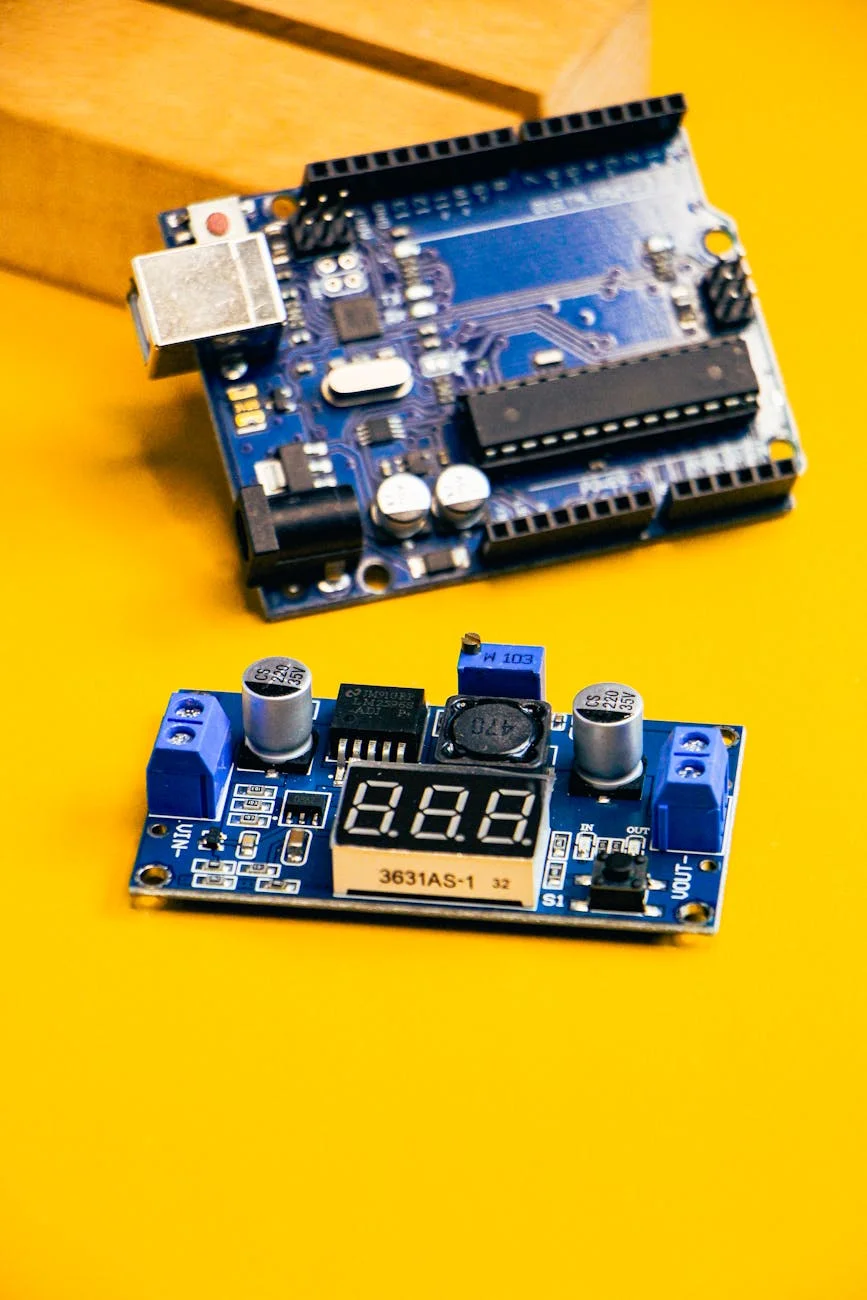
For home baristas who have ventured into building or modifying espresso machines with Arduino-controlled pumps, achieving precise and repeatable water flow is a primary objective. While these custom systems offer unparalleled control over extraction variables, they also introduce complexities. An unstable or inaccurate flow rate can undermine the entire purpose of such a project, leading to inconsistent shots and frustration. Understanding how to diagnose and resolve these issues is fundamental to mastering the hardware. This article provides a systematic guide to troubleshooting common water flow problems in these advanced setups, focusing on practical, effective solutions for the experienced user who is comfortable working with both hardware and software.
Systematic diagnosis: software vs. hardware
When flow becomes erratic, the first step is to determine whether the root cause lies in the physical hardware or the control software. Conflating the two can lead to wasted time and unnecessary component replacements. A logical approach is to isolate the pump and its immediate circuit from the complexities of the control loop.
A simple method is to bypass the primary control code. By uploading a basic Arduino sketch that allows you to manually set the pump’s duty cycle via the serial monitor, you can observe its behavior in an open-loop state. If the pump delivers a steady stream of water at various fixed power levels, the core hardware (pump, power supply, motor driver) is likely functioning correctly. In this case, the problem is almost certainly within the flow sensor, the PID algorithm, or the code’s logic. Conversely, if the flow is inconsistent even with a constant manual signal, the issue points to a hardware problem such as a failing pump, a compromised power supply, or blockages in the hydraulic path.
Flow meter calibration and data integrity
An accurate flow meter is the cornerstone of any closed-loop flow control system. The Arduino relies entirely on the data from this sensor to make decisions. Many users trust the manufacturer’s specified pulses-per-liter value, but this is often just a baseline. Real-world performance can be affected by water temperature, pressure, and manufacturing tolerances.
Proper calibration is non-negotiable. The process is straightforward:
- Write a simple sketch to count and display the pulses from the flow meter.
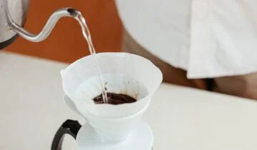
- Run a precise volume of water through the system, such as 500 mL, collecting it in a calibrated vessel.
- Divide the total pulse count by the volume dispensed (in liters) to get your specific calibration factor.
Beyond calibration, data integrity is critical. Electrical noise from the pump motor or power supply can interfere with the sensor’s signal, causing spurious readings. Ensure sensor wires are shielded and routed away from high-current lines. A small capacitor (e.g., 0.1 µF) placed across the sensor’s power and ground pins can also help filter out noise, leading to a more stable signal for the Arduino to process.
The impact of power delivery on pump stability
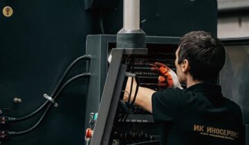
The stability of the pump’s output is directly tied to the quality of its power source. An inadequate or fluctuating power supply unit (PSU) is a frequent cause of flow issues that can be difficult to diagnose. The pump’s current draw changes with load (i.e., back pressure from the coffee puck), and the PSU must be able to deliver consistent voltage under these varying conditions.
If the PSU voltage sags when the pump is under load, the pump’s speed will decrease, causing a dip in flow that the software will then try to correct, often leading to oscillation. Using a high-quality, appropriately rated PSU is essential. Furthermore, the method used to drive the pump matters. A simple MOSFET setup provides basic on/off or PWM speed control, but a dedicated motor driver board can offer more stable and linear power delivery, translating to smoother pump operation and finer control over the flow rate.
Software logic and PID tuning for precision flow
Once hardware and sensor issues are ruled out, the focus shifts to the software, specifically the Proportional-Integral-Derivative (PID) control loop. A poorly tuned PID controller is one of the most common reasons for flow instability. It can cause the flow rate to overshoot the target, oscillate around it, or respond too slowly to changes.
Tuning a PID loop for a fluid system requires a methodical approach. It is often best to start by setting the Integral (I) and Derivative (D) terms to zero and focusing solely on the Proportional (P) term. Increase the P value until the flow begins to oscillate around the setpoint. This establishes the system’s baseline responsiveness. Next, slowly introduce the I term to eliminate the steady-state error and ensure the flow settles precisely on the target. The D term, which helps dampen overshoot, is often not required for espresso pumps and can sometimes introduce instability if not used carefully. Patience and incremental adjustments are key to achieving a stable, responsive system.
Conclusion
Troubleshooting water flow in a custom espresso machine requires a blend of hardware knowledge and software acumen. By systematically diagnosing issues, you can move from frustration to precision. The process begins with isolating the problem between hardware and software, followed by meticulous calibration of the flow sensor to ensure the system is working with accurate data. Verifying the integrity of the power supply and motor control circuit is equally important, as no amount of software tuning can compensate for unstable hardware. Finally, a careful and methodical approach to PID tuning allows the control system to perform with the stability and responsiveness required for high-quality espresso extraction. For those dedicated to refining their equipment, the necessary components and tools for these advanced projects are often available from specialized suppliers like papelespresso.com.
 No products in the cart.